Difference between revisions of "Using Cambam to make the Hackerspace Maker Coin"
Kaminmiller (talk | contribs) |
|||
| Line 44: | Line 44: | ||
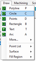
[[File:Circle Button on the Drawing Toolbar.png|Circle Button on the Drawing Toolbar]] | [[File:Circle Button on the Drawing Toolbar.png|Circle Button on the Drawing Toolbar]] | ||
| + | |||
[[File:Circle Button on the Drawing Dropdown Menu.png|Circle Button on the Drawing Dropdown Menu]] | [[File:Circle Button on the Drawing Dropdown Menu.png|Circle Button on the Drawing Dropdown Menu]] | ||
| Line 63: | Line 64: | ||
Press enter to confirm the 3 points, and go to the details pane to the left, and select the ellipsis to edit the point coordinates. | Press enter to confirm the 3 points, and go to the details pane to the left, and select the ellipsis to edit the point coordinates. | ||
| + | |||
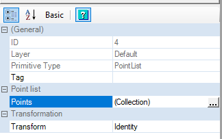
[[File:Point Reference Properties.png|Point Reference Details Pane]] | [[File:Point Reference Properties.png|Point Reference Details Pane]] | ||
| Line 89: | Line 91: | ||
| − | Move arc, reference top point of arc to top point of circle at 0,55.5,0 | + | === Move arc, reference top point of arc to top point of circle at 0,55.5,0 === |
| + | Now we will align the top of the arc with the top reference point we made. | ||
| + | |||
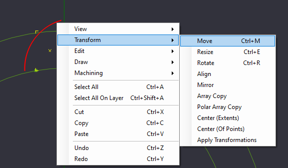
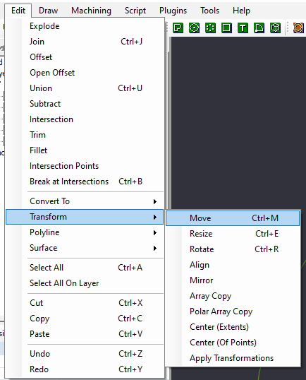
| + | Select the Arc we created, and select from the Transform menu to move the arc. You can access Transform from the Right-Click Menu, or from the Edit->Transform Menu. | ||
| + | |||
| + | [[File:Move Right Click Menu.png|Move Right Click Menu]] | ||
| + | [[File:Move Edit Menu.png|Move Edit Menu]] | ||
| + | |||
| + | After you select the move command, you need to select the reference point to start the move from. Select the top of the arc. | ||
| + | |||
| − | |||
Revision as of 08:54, 4 June 2019
Currently Incomplete - Kamin Miller - 6-3-2019
Using this tutorial, you should be able to create the line drawings in CamBam that is used to create the Gainesville Hackerspace Maker Coin.
Open the CamBam plus Application.
As of this writing, it is version 0.9.8
Set the document units to Millimeters
Using millimeters allows us easier access to some of the scaling options. The K40 Laser also defaults to using millimeters for units.
Create a point at the origin 0,0,0
Creating a point at the origin allows us to easily base some of our geometry around an easy to reference number (0,0,0)[That is, 0{zero} units away from the X, Y, and Z planes]
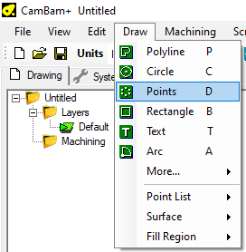
Select the button to draw a Point List from the toolbar, select it from the Draw Menu, or use the keyboard shortcut 'D'.
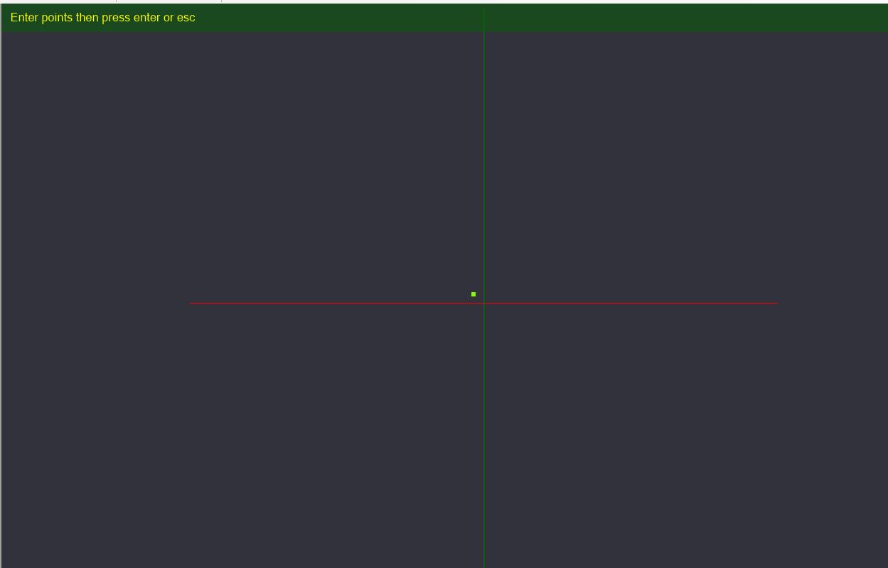
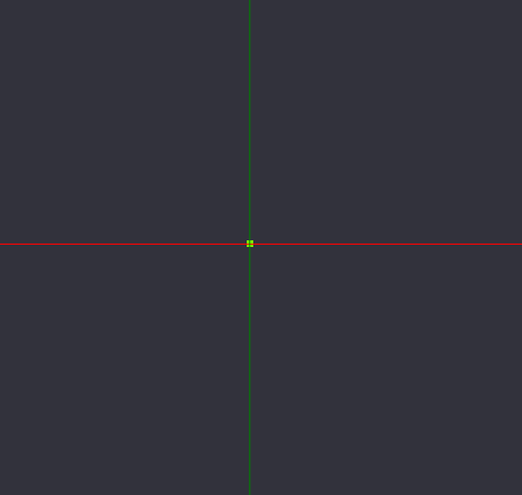
Place a point on the Canvas. It does not need to be at the exact center (where the Green and Red lines intersect). Press enter to complete your point placement.
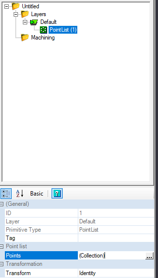
Once the point is placed, on the details pane to the left, we see an object in the browser called "PointList", and we can click the ellipsis(...) on the Point list property to pull up the coordinate box of the point we just placed.
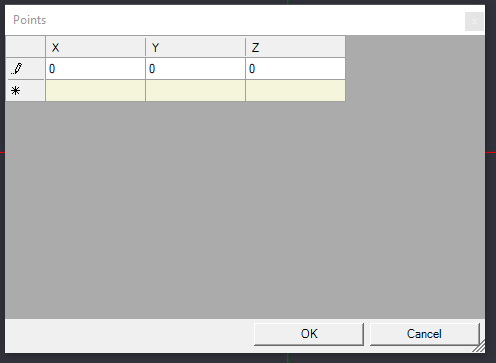
We can set the X, Y, and Z coordinates to 0, and click OK to save our changes. On the canvas, we can see the point we created has adjusted its location to the center.
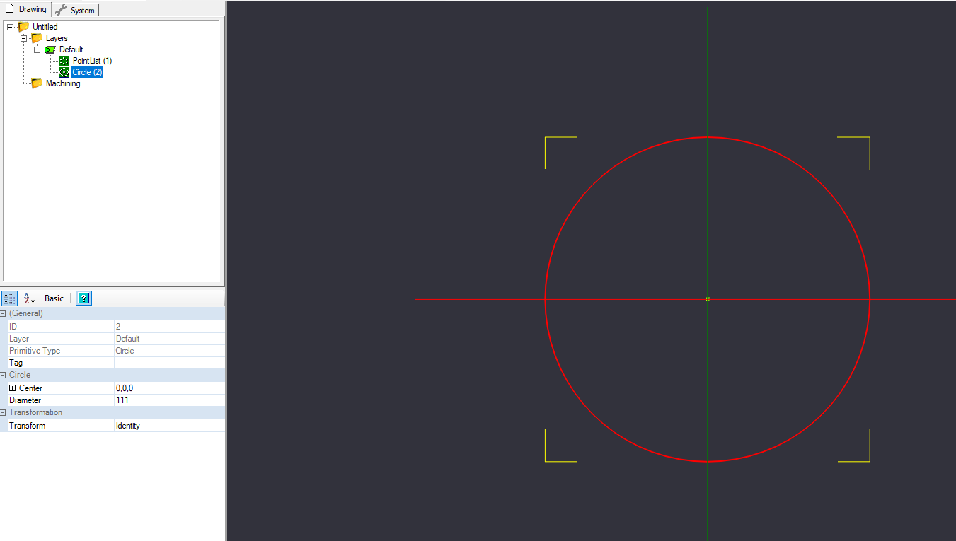
Create Circle, Diameter 111mm – Center at 0,0,0
Now we need to draw some reference geometry. Let's draw the outer boundaries of the shape we will ultimately create.
You will need to draw a circle that is 111mm in diameter, with the center point being the center of our work space (0,0,0).
When you click the circle button, you click on the canvas where you want to place the center of the circle. You should be able to snap it to the center point we created above. Click again to set the diameter of the circle in the canvas. Once the circle is drawn, in the details pane to the left, verify the center is listed as (0,0,0), and the diameter is 111.
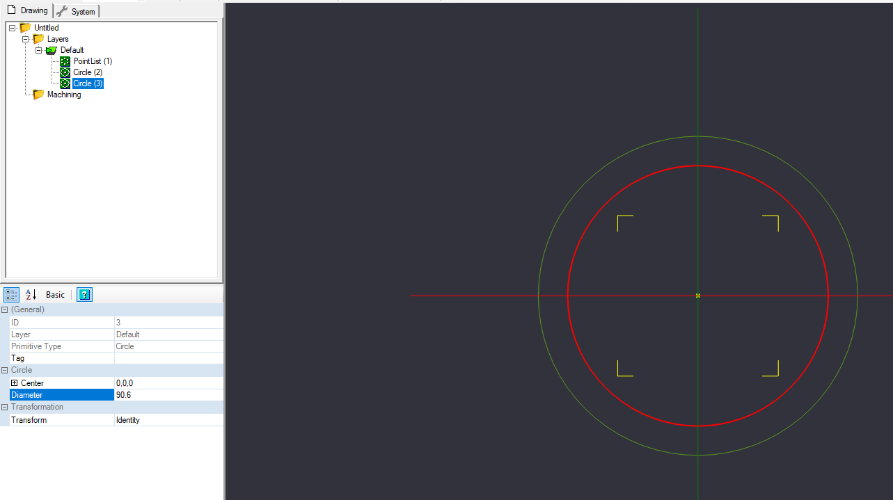
Create Circle, diameter 90.6mm – center at 0,0,0
We will create a 2nd circle for reference, similar to the previous circle, with the center at (0,0,0), but a diameter of 90.6mm.
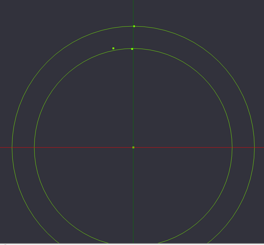
Create points at 0,55.5,0 & 0,44.62,0 & -7.8, 44.62,0
We will need to create 3 more reference points for the next step. Select Point List from the Toolbar, Draw Menu, or keyboard shortcut, and place 3 points in a backwards L shape near the top of outer circle, the top of the inner circle, and to the left of the previous point.
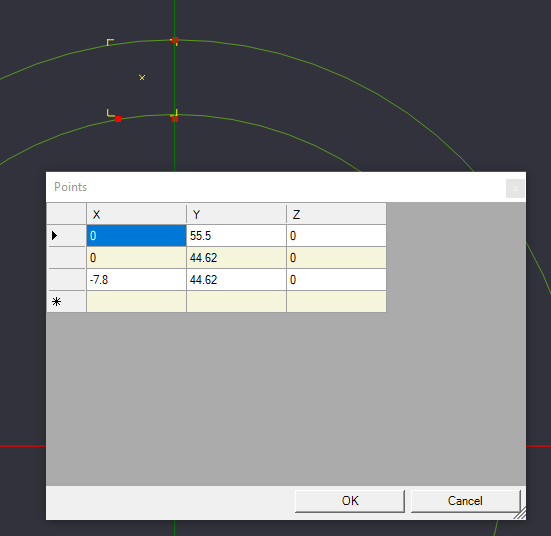
Press enter to confirm the 3 points, and go to the details pane to the left, and select the ellipsis to edit the point coordinates.
Set the 3 points to (0,55.5,0)[The top of the outer circle {Diameter of Outer Circle \ 2}], (-7.8, 44.62,0)[Point on the inner circle, just to the left], and (0,44.62,0)[Point perpendicular to the previous point].
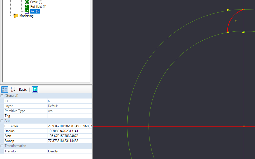
Create arc, points at 0,55.5,0 -7.8,44.62,0 Radius 13.7
Now we will use the points we just created to create an arc for our drawing.
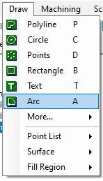
Start by selecting Arc from the Toolbar or Drawing Menu.
Our beginning point will be the reference point we arranged to be the top of the reference circle. The end point will be the bottom left reference point we made, and the arc radius point will be the bottom right reference point we made.
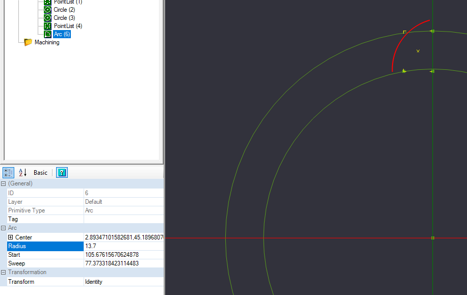
In the details pane of your arc, some of your data might not match what is in the reference image, and that is OK. Change the radius to be 13.7. After changing the number and pressing enter, the arc may move from its drawn position. We will correct that in the next step.
Move arc, reference top point of arc to top point of circle at 0,55.5,0
Now we will align the top of the arc with the top reference point we made.
Select the Arc we created, and select from the Transform menu to move the arc. You can access Transform from the Right-Click Menu, or from the Edit->Transform Menu.
After you select the move command, you need to select the reference point to start the move from. Select the top of the arc.
Mirror Arc, select arc, set top point to top of arc, draw line down to next point to make mirror line
Polar Array Copy, 15 copies(16 total) rotation axis 0,0,22.5
Circle 3.2mm diameter. Move by snapping to center, place tangent on lines
Select lines + circle, break at intersections, tolerance of .1
Delete overlap
Polar array copy arc, 15 copies, rotation axis 0,0,22.5
Delete Outer & Inner Circle & Point Lists except Center
Select all, break at intersections
Trim up unused geometry
Select all, join, tolerance .1
Should have 2 objects, PolyLine & Pointlist
Open new instance of cambam Open Logo.dxf Copy Logo to clipboard, paste into design.
Move to center
Resize, use final size to make Y dimension 60-75mm
Draw Circle around logo.
Done


